Zero to CNC
Last year I found myself with some free time and decided to try learning some basic woodworking skills. Using hand-held tools quickly reminded me of my ineptitude for craftsmanship, so I was drawn to CNC routing.
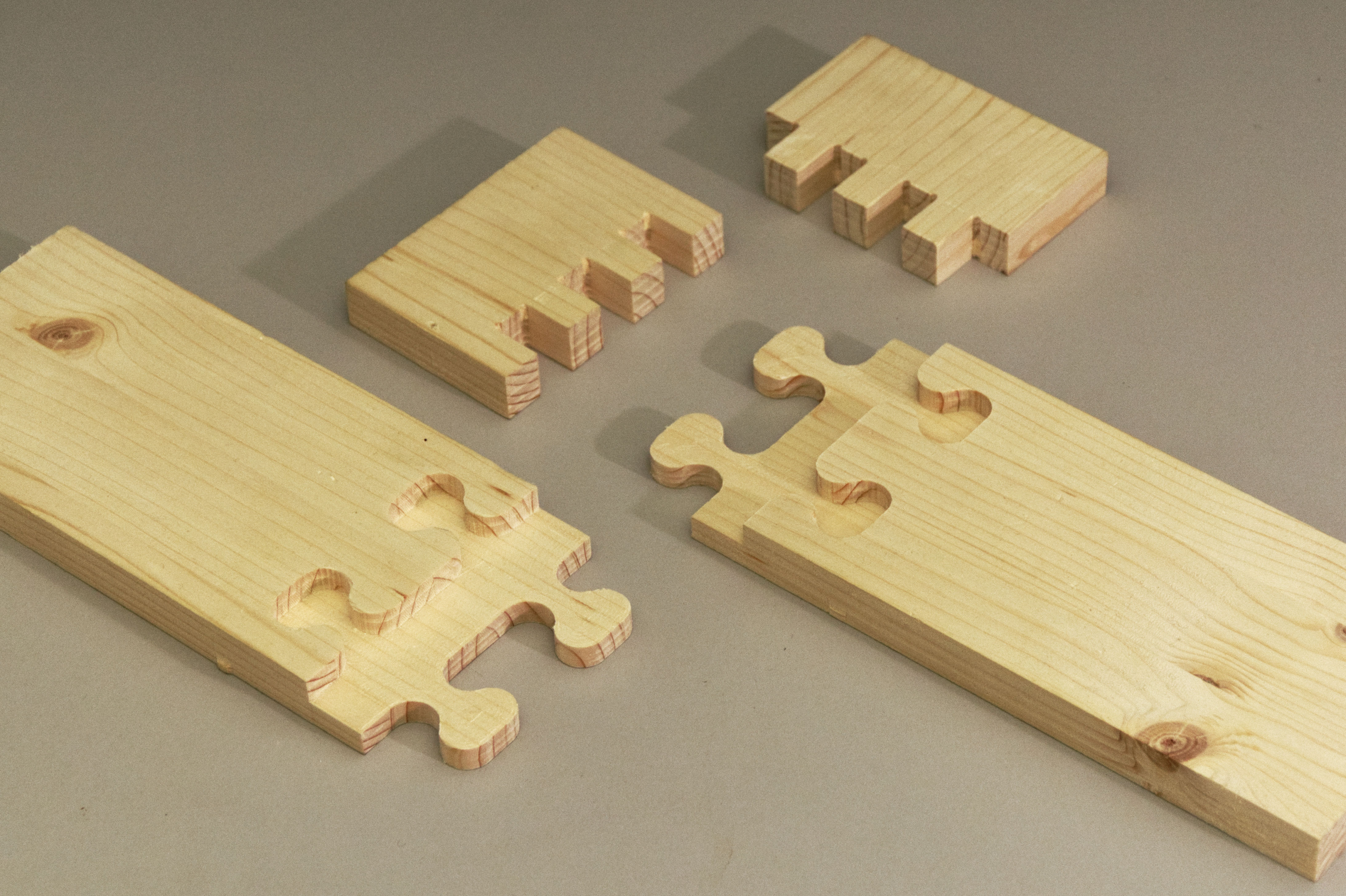
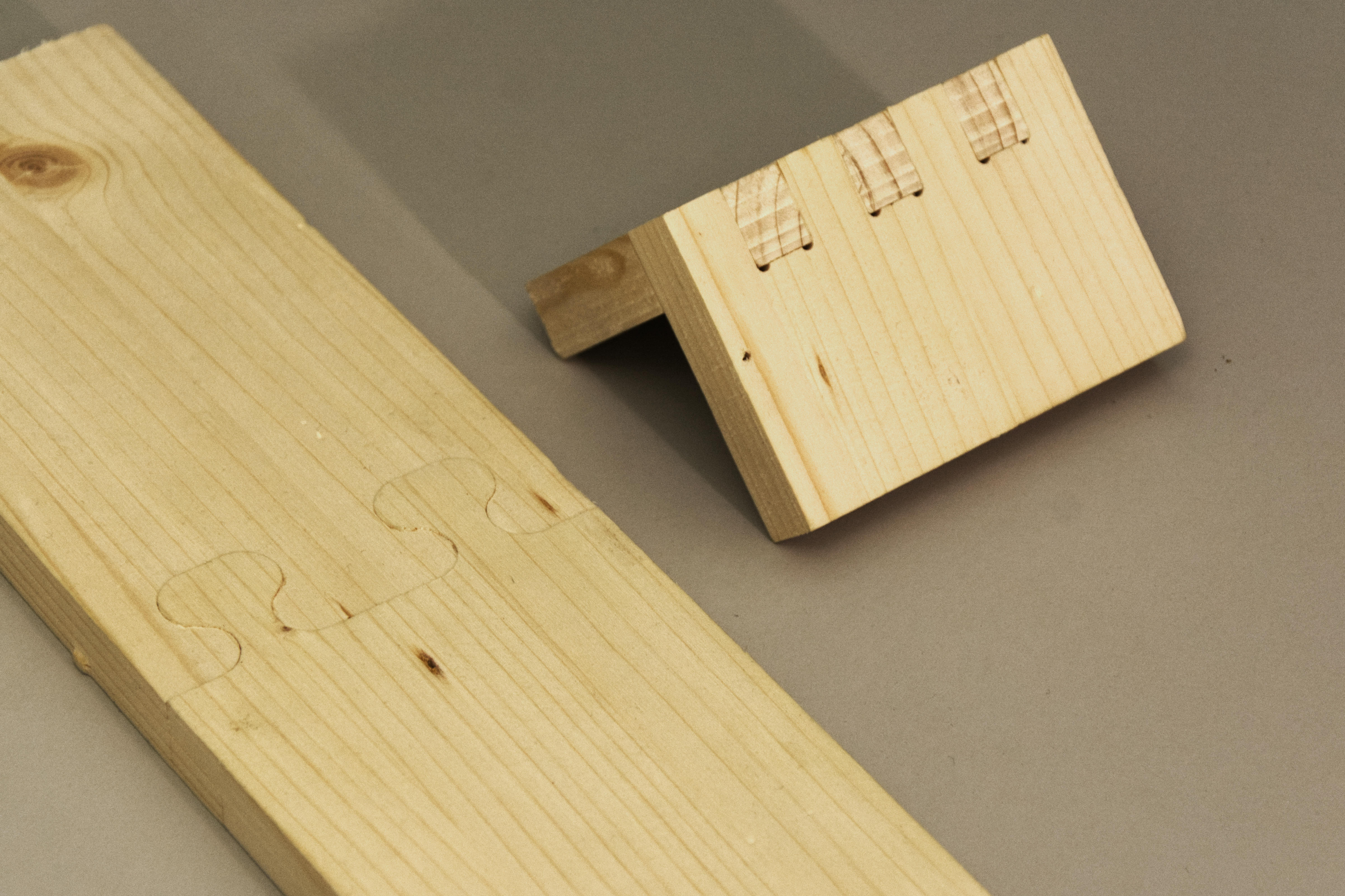
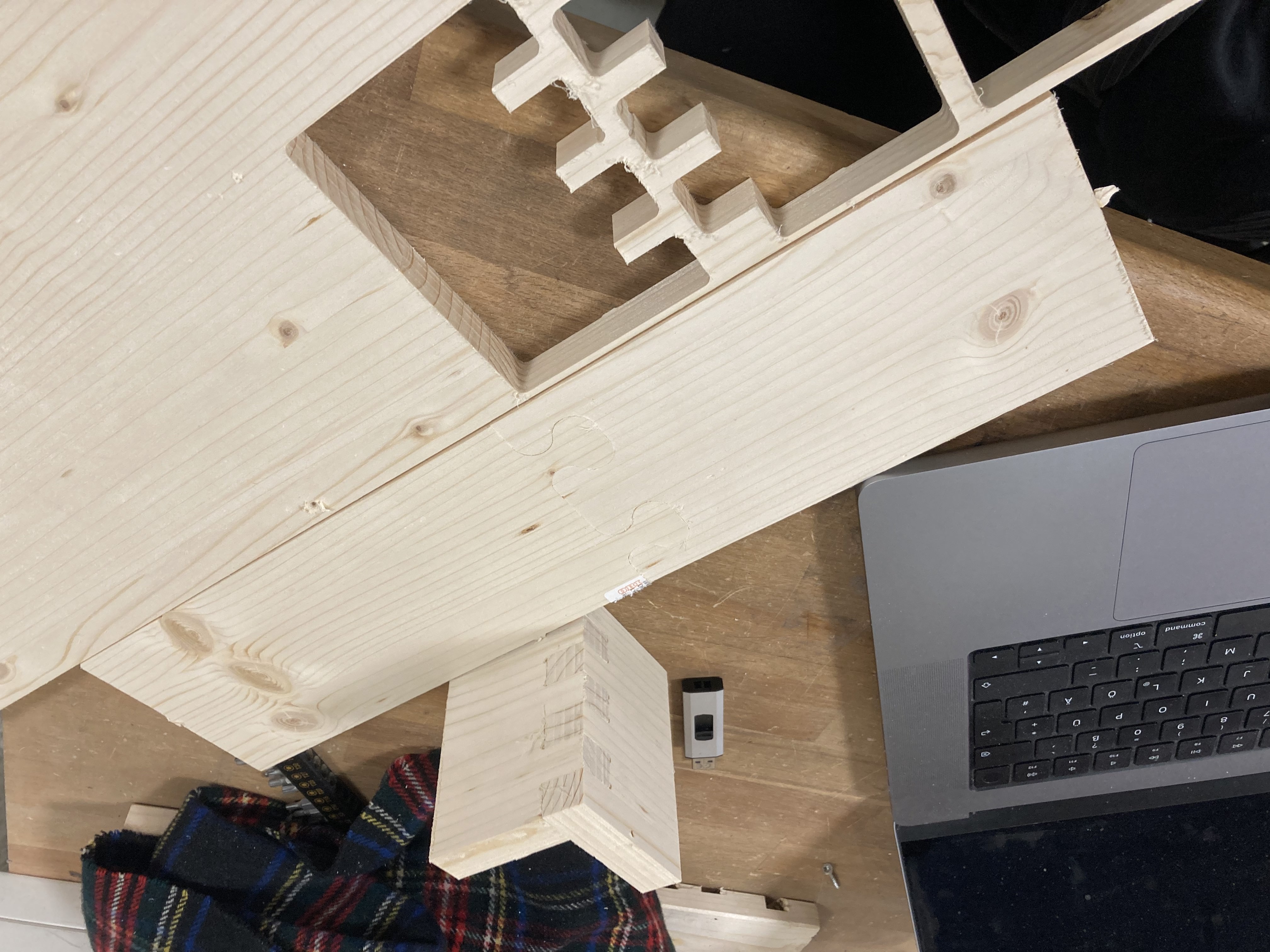
As a first humble project, I decided to make some commonly used joints between two pieces of wood. This is what they look like:
What was surprisingly hard about this project was that while tutorials were available for each step of the way none was giving you an overview from start to finish. This post explains how I got here. The aim here is less to be a detailed instruction manual - those already exist and are linked to - but more of a strategy guide bringing everything together.
Step 0: Theory
Let’s for a moment revisit what a CNC router is and does. This is a fairly typical hobbyist-level CNC router:
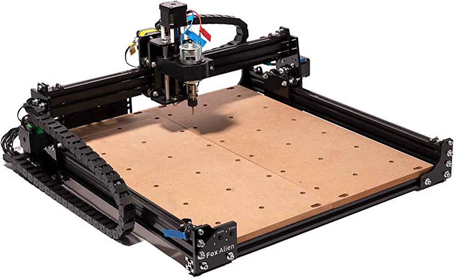
The main part of a CNC router is a rotating routing bit. Think of it as a drill bit that can not only cut down through a material but also sideways. If you put this into a power drill and, unlike me, are a good craftsman, you can cut arbitrary stuff out of wood with it. A CNC router is doing the same. Its sole purpose is moving the router bit around with superhuman precision.
It does this with some stepper motors, electric motors that know their orientation, and, with some calibration and clever software, the position of the moving pieces they control.
CNC routers are grouped by the ways they can move. For instance, the above image depicts a 3-axis router.
This one can go:
- back and forth, using the long rails on the sides
- left and right, using the rail across, on which the routing sub-assembly is mounted, and
- up and down, using the long screw you can barely see behind the routing head
It notably cannot turn its head along any axis. You can get a router that can do arbitrary movements for enough money, but let’s stay with this one for now.
Ok, but how does the router know what to cut?
It follows instructions such as this:
G17 G20 G90 G94 G54
G0 Z0.25
X-0.5 Y0.
Z0.1
G01 Z0. F5.
G02 X0. Y0.5 I0.5 J0. F2.5
X0.5 Y0. I0. J-0.5
X0. Y-0.5 I-0.5 J0.
X-0.5 Y0. I0. J0.5
G01 Z0.1 F5.
G00 X0. Y0. Z0.25
This is machine code, called G-code, encoding movement on the three axes the router can move in. In the line G02 X0. Y0.5 I0.5 J0. F2.5, for example, G02 means “do a circular interpolation in a clockwise direction”, X0. Y0.5 are the absolute coordinates of the endpoint of the arc, I0.5 J0. are the relative coordinates of the center of the arc, and F2.5 indicates the speed of the router relative to some basic unit. So the line tells the router to follow a quarter circle. The entire code above encodes cutting a circle of one unit (cm, inch, whatever the router was calibrated to) diameter.
We do not want to write this code by hand. It is typically generated by a compiler from a model of the object to cut, similar to how an executable is compiled from human-readable code. So we need to start with modeling.
Step 1: Modelling
Modeling means making a plan for the thing we want to make. For CNC routing several types of abstractions appear to be useful:
- a 2D model, i.e., a sketch, of the path the router would follow
- a 2D sketch including not only paths but entire areas the router should clear
- a 3D model of the entire object we wish to create
These options follow an ascending level of abstraction: The first option is just a visual representation of the G-code in 2 dimensions, i.e., implying a constant cutting depth. The second option leaves the calculation of the optimal path to clear a solid area of material to the compiler. The third also requires the compiler to determine the depth of different cuts.
I decided to go with the final one since it abstracts away as much tedious work as possible. Another plus is that 3D modeling is useful for all kinds of projects, not just CNC routing.
The problem was that I knew zero modeling. So next up was finding the right software and learning the basics.
There are many great programs for 3D modeling. I did zero research and trusted my friends who recommended Fusion 360. It turned out to have all that I need, including a “Manufacture” context that can generate router-ready G-Code from models with little extra work. While it is not primarily designed for woodworking and can be quite slow (we are cracking a nut with a sledgehammer here) its general-purpose usefulness is a plus in my book. That being said, maybe there is a better tool for you.
Here are some of the resources I used to learn general 3D modeling with Fusion 360:
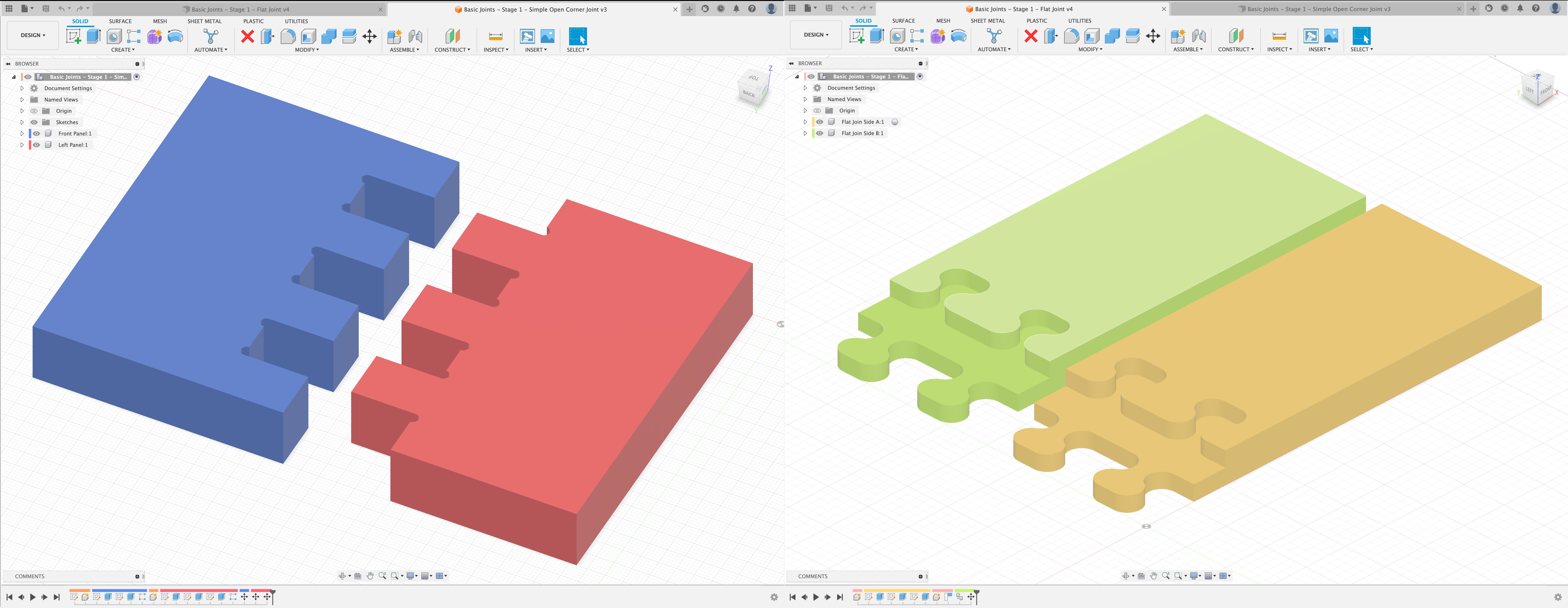
These were more than sufficient for a simple project. After a handful of the exercises, you should easily be able to replicate my models:
Before we move on to generating G-Code, I want to highlight one modeling feature of Fusion 360 here that people might otherwise overlook, but in my opinion is essential: construction parameters.
Parameters let you change the dimensions of your models on the fly. Because Fusion 360 is functional (in the Computer Science sense of functional, meaning the finished model is the result of applying operations, one after another, starting with the first sketch) very complex things can be achieved by simply changing a parameter. Changing a parameter in Fusion feels similar to changing a variable in a complicated Excel sheet and watching the results recompute.
This is practical in several ways: For one, you can play with the finished model to find a visual style you like. You can also start planning a project without knowing its exact dimension. You can make a range of things (for example, differently sized drawers), simply by changing some variables in a finished model.
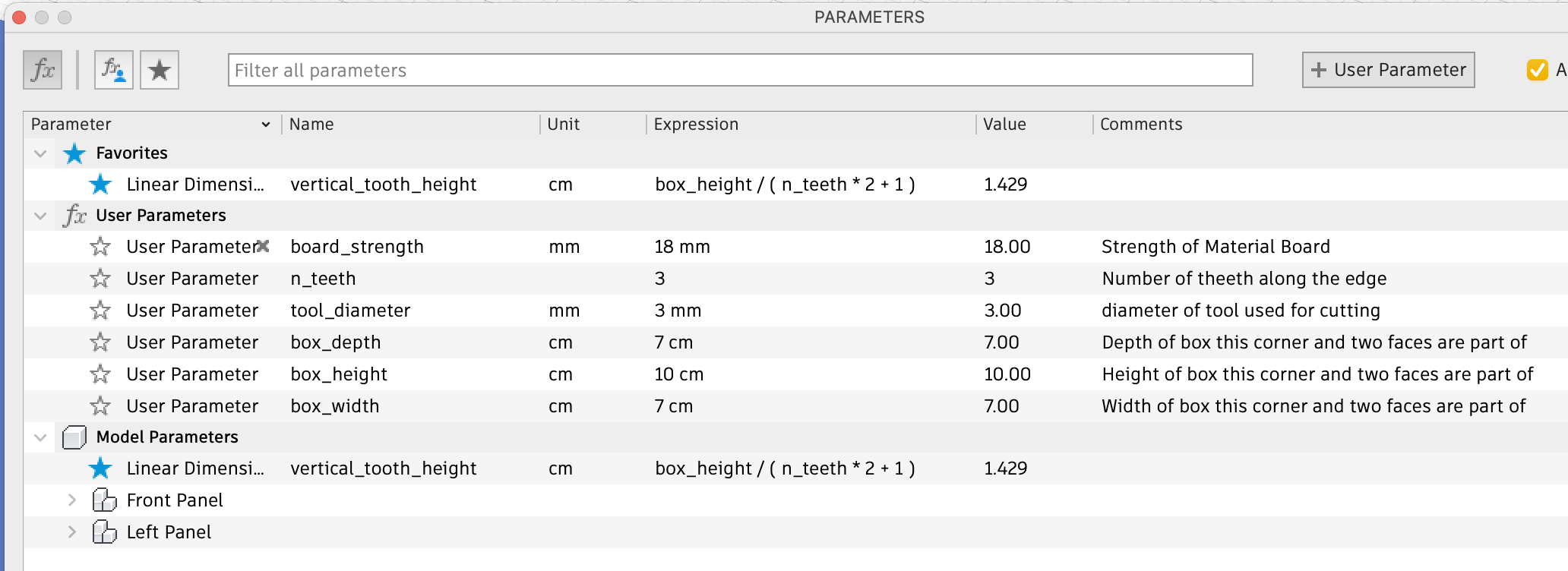
Here you can see some of the parameters of the second model above. As you can see, the parameters can even reference each other. Here are 3 different versions of the same model with different parameters.
Now that I have convinced you to try using parameters in Fusion, let’s move on.
Step 2: Model to G-Code
To get our router to cut the models we just made, we have to somehow compile them into the instructions from step 0. Luckily, as I have mentioned above, Fusion can do this for us too: We simply need to switch to the “Manufacturing” context. Next, we need to tell Fusion where we need to cut. Here are some resources that can help you with this:
- great tutorial introducing all the basic operations
- another tutorial explaining the basics
- tutorial for 3D sculpting (not needed for this project, but fun)
One non-obvious thing you need to know for this step is the routing bits you are going to use. I bought mine here. This project was entirely cut with a cheap 3mm universal bit, although for later projects I used dedicated wood bits. It’s fairly simple to add these bits to the Fusion 360 tool library. Don’t worry if you do not know all the measurements Fusion asks of you, if you know the diameter and total length below the holder and the shape looks about right, you’re good. Here’s a pdf that helps you calculate the cutting speed Fusion wants to know. If this is your first project it’s a good idea to half all the values.
Now that all the routing paths have been drawn by Fusion 360 and you have checked with the simulation feature that everything looks O.K., there is a final obstacle to getting the G-Code: You need to know which “flavor” of G-Code your router wants, and for that, you need to know which router you are going to be working with. I used this router at the Happylab Comaking Space in Berlin. The wiki article of the co-making space tells us it needs the “Eding CNC” G-code, and indeed it is part of Fusion 360’s long list of installable compiler libraries. Once we install and run this, the G-code comes out.
Step 3: Physically using the router
Now that we have solved the issue of telling the router what to do, we can get back to physical routing. Roughly, here is the process:
- You boot the router. There usually is a PC controlling the router, which you start as well.
- There is a control program on the router PC. Use it to start the router’s calibration run, which will initialize the software to track the current position of the drill bit.
- Fix the piece of wood you’re cutting from to the router, either with clamps or by screwing it onto a larger, “sacrificial” piece already clamped down. I prefer the second option since the screws don’t get into the way as much as the clamps.
- Insert the routing bit.
- Use the software and/or the controls of the router to move the router to the origin point of your routing setup (in my case, the center of the wood plate I cut from). I use a piece of paper to check that the routing bit touches the surface.
- Set all coordinates to zero here. This will align the origin point of the router with that of your G-code.
- Load your G-code into the router control program. A path preview should show up in the routing program.
- Move the routing bit around to the edges of the previewed paths (its position should show up in the program, too). This will give you an idea of where the bit will move and whether it will hit anything (a clamp, for example) or leave the material at any point.
- Start the program. Do not sit back and watch. Keep the controls ready to slow down or pause the program if something goes wrong.
The specifics of this step will depend on your router setup. Still, here are some resources:
- A wiki page for the router I used, including multiple video tutorials
- How to insert the tool into the tool holder
- A helpful youtube tutorial for setting up the router (skip to 9:27)
Step 4: Profit
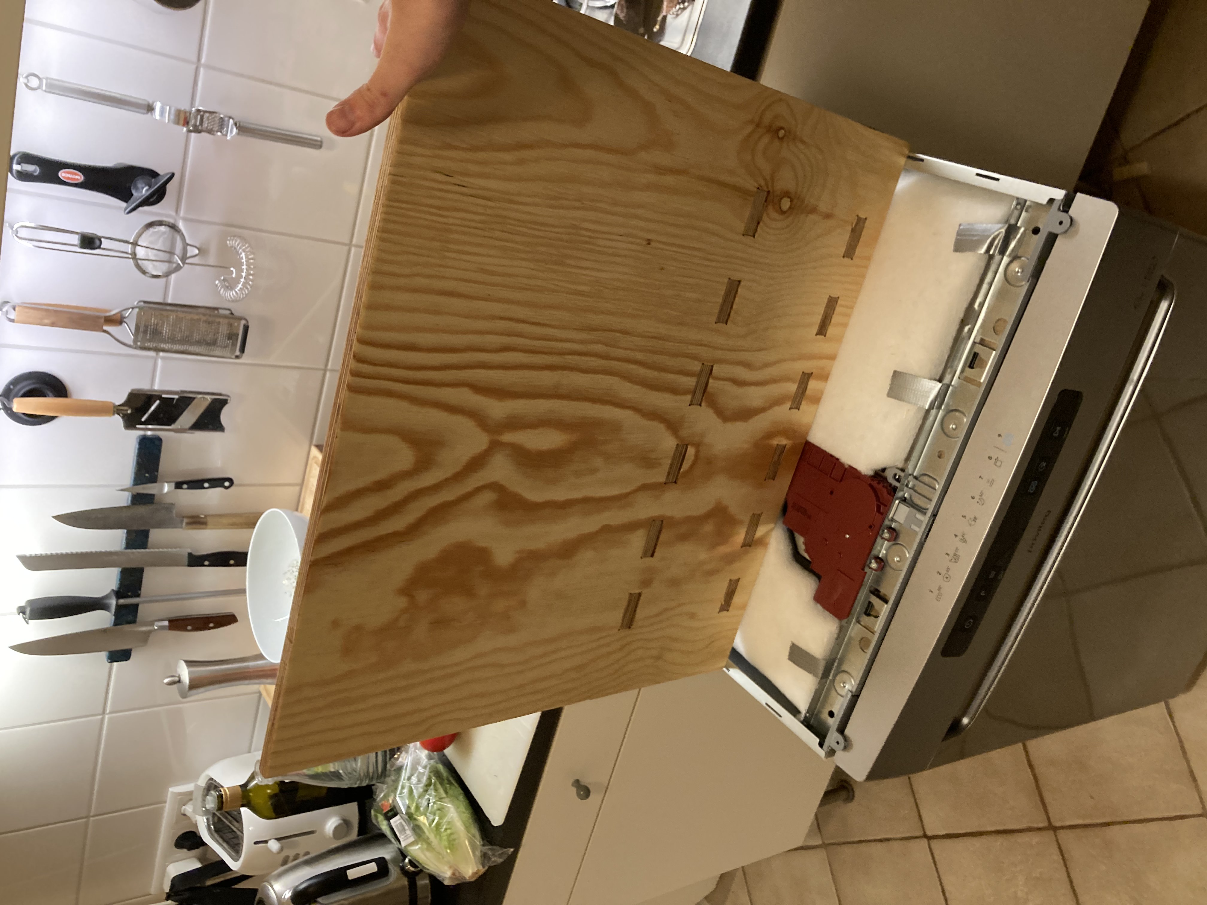
After the router has finished, you can remove the piece from the router, cut away the tabs holding your piece … and you are finished. Congratulations, you went from zero to CNC.
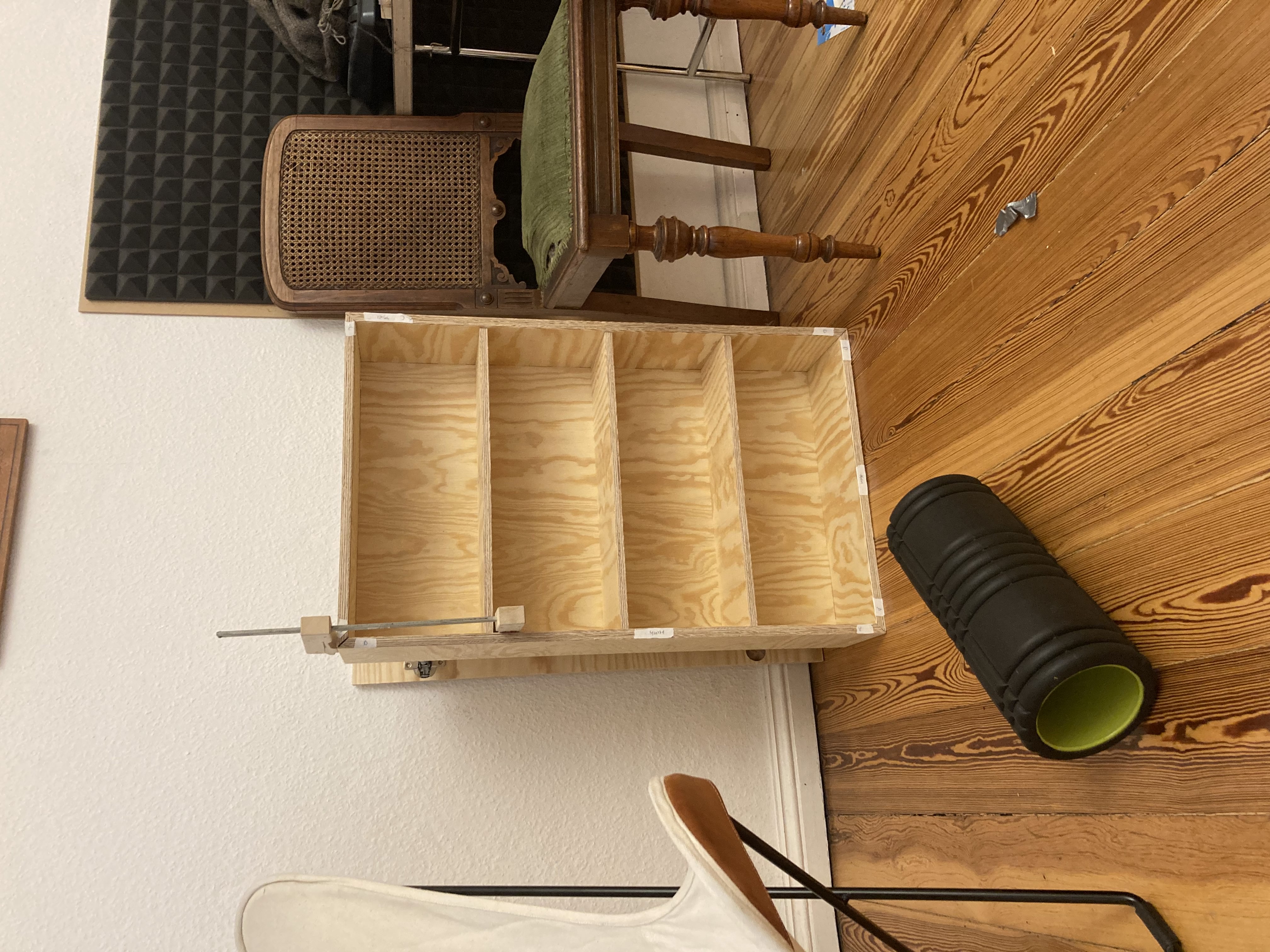
Moving on to more complex projects is now just a matter of experience. The hardest part is done. For inspiration, here are 2 things I have made since making the step from zero to CNC: